
Berikut ini desain dan rancang bangun pembuatan robot dengan kontrol berbasis
wireless menggunakan gelombang 315 MHz.

Gambar 1. Contoh aplikasi remote kontrol wireless
Untuk membangun sistem kontrol wireless diperlukan dua buah sistem
mikrokontroler yang terhubung secara serial. Satu sistem sebagai robot penerima
perintah atau receiver (Rx),
sedangkan sistem kontrol robot memberikan perintah atau transmitter (Tx). Dalam mikrokontroler keluarga AVR, komunikasi
serial terdapat pada menu USART (Universal
Syncronous Asyncronous Receiver/Transmitter).
Simulasi
Sistem Wireless Proteus
Untuk membuat simulasi wireless di proteus, dapat kita lakukan
dengan menghubungkan sistem transmitter dan
receiver mikrokontroler dengan
komponen optocoupler yang sebenarnya
menghubungkan tapi tidak secara langsung. Berikut adalah desain simulasi
proteus sistem wireless robot kontrol
digital.

Gambar 2. Skema proteus robot
kontrol digital wireless
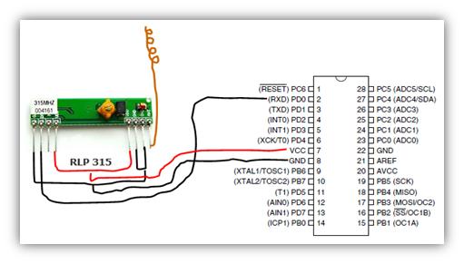
Untuk membuat robot actual dari skema
tersebut, maka optocoupler diganti
dengan komponen TLP 315 MHz di bagian Transmitter
remote kontrol dan RLP 315 MHz di bagian Receiver Robot.
Hardware
Aktual TLP/RLP 315 MHz

Transmitter

Receiver
PROGRAM CV AVR REMOTE CONTROL (TRANSMITTER)
Sesuai dengan desain hardware rangkaian, berikut adalah program CV AVR untuk remote control robot.
/*****************************************************
This program was produced by the
CodeWizardAVR V2.05.0 Professional
Automatic Program Generator
© Copyright 1998-2010 Pavel Haiduc, HP
InfoTech s.r.l.
http://www.hpinfotech.com
Project : Remote Kontrol Robot Kontrol
Wireless
Version : I Hexapod UHF
Date
: 9/16/2012
Author
: Mada Sanjaya WS, Ph.D
Company : Bolabot Techno Robotic School
Comments: "Semangat harapan itu masih
ada"
Chip type : ATmega8
Program type : Application
AVR Core Clock frequency: 12.000000 MHz
Memory model : Small
External RAM size : 0
Data Stack size : 256
*****************************************************/
#include <mega8.h>
// Standard Input/Output functions
#include <stdio.h>
#include <delay.h>
unsigned char perintah;
// Declare your global variables here
void main(void)
{
// Declare your local variables here
// Input/Output Ports initialization
// Port B initialization
// Func7=In Func6=In Func5=In Func4=In
Func3=In Func2=In Func1=In Func0=In
// State7=T State6=T State5=T State4=T
State3=T State2=T State1=T State0=T
PORTB=0x00;
DDRB=0x00;
// Port C initialization
// Func6=In Func5=In Func4=In Func3=In
Func2=In Func1=In Func0=In
// State6=T State5=T State4=T State3=T
State2=T State1=T State0=T
PORTC=0x00;
DDRC=0x00;
// Port D initialization
// Func7=In Func6=In Func5=In Func4=In
Func3=In Func2=In Func1=In Func0=In
// State7=T State6=T State5=T State4=T
State3=T State2=T State1=T State0=T
PORTD=0x00;
DDRD=0x00;
// Timer/Counter 0 initialization
// Clock source: System Clock
// Clock value: Timer 0 Stopped
TCCR0=0x00;
TCNT0=0x00;
// Timer/Counter 1 initialization
// Clock source: System Clock
// Clock value: Timer1 Stopped
// Mode: Normal top=0xFFFF
// OC1A output: Discon.
// OC1B output: Discon.
// Noise Canceler: Off
// Input Capture on Falling Edge
// Timer1 Overflow Interrupt: Off
// Input Capture Interrupt: Off
// Compare A Match Interrupt: Off
// Compare B Match Interrupt: Off
TCCR1A=0x00;
TCCR1B=0x00;
TCNT1H=0x00;
TCNT1L=0x00;
ICR1H=0x00;
ICR1L=0x00;
OCR1AH=0x00;
OCR1AL=0x00;
OCR1BH=0x00;
OCR1BL=0x00;
// Timer/Counter 2 initialization
// Clock source: System Clock
// Clock value: Timer2 Stopped
// Mode: Normal top=0xFF
// OC2 output: Disconnected
ASSR=0x00;
TCCR2=0x00;
TCNT2=0x00;
OCR2=0x00;
// External Interrupt(s) initialization
// INT0: Off
// INT1: Off
MCUCR=0x00;
// Timer(s)/Counter(s) Interrupt(s)
initialization
TIMSK=0x00;
// USART initialization
// Communication Parameters: 8 Data, 1
Stop, No Parity
// USART Receiver: Off
// USART Transmitter: On
// USART Mode: Asynchronous
// USART Baud Rate: 1200
UCSRA=0x00;
UCSRB=0x08;
UCSRC=0x86;
UBRRH=0x02;
UBRRL=0x70;
// Analog Comparator initialization
// Analog Comparator: Off
// Analog Comparator Input Capture by
Timer/Counter 1: Off
ACSR=0x80;
SFIOR=0x00;
// ADC initialization
// ADC disabled
ADCSRA=0x00;
// SPI initialization
// SPI disabled
SPCR=0x00;
// TWI initialization
// TWI disabled
TWCR=0x00;
// mendefinisikan input output
DDRD.5=0; //input
tombol perintah belok kiri
DDRD.6=0; //input
tombol perintah belok kanan
DDRD.7=0; //input
tombol perintah mundur
DDRB.0=0; //input
tombol perintah maju
DDRD.2=1; //output
led indikator ketika tombol ditekan
while (1)
{
if (PINB.0!=0)
//program maju
{
perintah=1;
PORTD.2=0;
}
else if
(PIND.7!=0)
//program mundur
{
perintah=2;
PORTD.2=0;
}
else if
(PIND.6!=0)
//program belok
kanan
{
perintah=3;
PORTD.2=0;
}
else if
(PIND.5!=0)
//program belok
kiri
{
perintah=4;
PORTD.2=0;
}
else
{
perintah=0; //
diam
PORTD.2=1;
}
putchar(perintah); // mengirim tipe data perintah
}
}
PROGRAM CV AVR ROBOT KONTROL DIGITAL (RECEIVER)
/*****************************************************
This program was produced by the
CodeWizardAVR V2.05.0 Professional
Automatic Program Generator
© Copyright 1998-2010 Pavel Haiduc, HP
InfoTech s.r.l.
http://www.hpinfotech.com
Project : Receiver Robot Kontrol Wireless
Version : I Hexapod
Date
: 9/16/2012
Author
: Mada Sanjaya WS, Ph.D
Company : Bolabot Techno Robotic School
Comments: "Semangat Harapan itu Masih
Ada!!!"
Chip type : ATmega8
Program type : Application
AVR Core Clock frequency: 12.000000 MHz
Memory model : Small
External RAM size : 0
Data Stack size : 256
*****************************************************/
#include <mega8.h>
#ifndef RXB8
#define RXB8 1
#endif
#ifndef TXB8
#define TXB8 0
#endif
#ifndef UPE
#define UPE 2
#endif
#ifndef DOR
#define DOR 3
#endif
#ifndef FE
#define FE 4
#endif
#ifndef UDRE
#define UDRE 5
#endif
#ifndef RXC
#define RXC 7
#endif
#define FRAMING_ERROR (1<<FE)
#define PARITY_ERROR (1<<UPE)
#define DATA_OVERRUN (1<<DOR)
#define DATA_REGISTER_EMPTY (1<<UDRE)
#define RX_COMPLETE (1<<RXC)
unsigned char dataku;
// mendefinisikan data
// USART Receiver buffer
#define RX_BUFFER_SIZE 8
char rx_buffer[RX_BUFFER_SIZE];
#if RX_BUFFER_SIZE <= 256
unsigned char
rx_wr_index,rx_rd_index,rx_counter;
#else
unsigned int
rx_wr_index,rx_rd_index,rx_counter;
#endif
// This flag is set on USART Receiver
buffer overflow
bit rx_buffer_overflow;
// USART Receiver interrupt service routine
interrupt [USART_RXC] void
usart_rx_isr(void)
{
char status,data;
status=UCSRA;
data=UDR;
if ((status & (FRAMING_ERROR |
PARITY_ERROR | DATA_OVERRUN))==0)
{
rx_buffer[rx_wr_index++]=data;
#if RX_BUFFER_SIZE == 256
// special case for receiver buffer size=256
if
(++rx_counter == 0)
{
#else
if
(rx_wr_index == RX_BUFFER_SIZE) rx_wr_index=0;
if
(++rx_counter == RX_BUFFER_SIZE)
{
rx_counter=0;
#endif
rx_buffer_overflow=1;
}
}
}
#ifndef _DEBUG_TERMINAL_IO_
// Get a character from the USART Receiver
buffer
#define _ALTERNATE_GETCHAR_
#pragma used+
char getchar(void)
{
char data;
while (rx_counter==0);
data=rx_buffer[rx_rd_index++];
#if RX_BUFFER_SIZE != 256
if (rx_rd_index == RX_BUFFER_SIZE)
rx_rd_index=0;
#endif
#asm("cli")
--rx_counter;
#asm("sei")
return data;
}
#pragma used-
#endif
// Standard Input/Output functions
#include <stdio.h>
// Declare your global variables here
void main(void)
{
// Declare your local variables here
// Input/Output Ports initialization
// Port B initialization
// Func7=In Func6=In Func5=In Func4=In
Func3=In Func2=Out Func1=Out Func0=In
// State7=T State6=T State5=T State4=T
State3=T State2=0 State1=0 State0=T
PORTB=0x00;
DDRB=0x06;
// Port C initialization
// Func6=In Func5=In Func4=In Func3=In
Func2=In Func1=In Func0=In
// State6=T State5=T State4=T State3=T
State2=T State1=T State0=T
PORTC=0x00;
DDRC=0x00;
// Port D initialization
// Func7=In Func6=In Func5=In Func4=In
Func3=In Func2=In Func1=In Func0=In
// State7=T State6=T State5=T State4=T
State3=T State2=T State1=T State0=T
PORTD=0x00;
DDRD=0x00;
// Timer/Counter 0 initialization
// Clock source: System Clock
// Clock value: Timer 0 Stopped
TCCR0=0x00;
TCNT0=0x00;
// Timer/Counter 1 initialization
// Clock source: System Clock
// Clock value: 11.719 kHz
// Mode: Fast PWM top=0x00FF
// OC1A output: Non-Inv.
// OC1B output: Non-Inv.
// Noise Canceler: Off
// Input Capture on Falling Edge
// Timer1 Overflow Interrupt: Off
// Input Capture Interrupt: Off
// Compare A Match Interrupt: Off
// Compare B Match Interrupt: Off
TCCR1A=0xA1;
TCCR1B=0x0D;
TCNT1H=0x00;
TCNT1L=0x00;
ICR1H=0x00;
ICR1L=0x00;
OCR1AH=0x00;
OCR1AL=0x00;
OCR1BH=0x00;
OCR1BL=0x00;
// Timer/Counter 2 initialization
// Clock source: System Clock
// Clock value: Timer2 Stopped
// Mode: Normal top=0xFF
// OC2 output: Disconnected
ASSR=0x00;
TCCR2=0x00;
TCNT2=0x00;
OCR2=0x00;
// External Interrupt(s) initialization
// INT0: Off
// INT1: Off
MCUCR=0x00;
// Timer(s)/Counter(s) Interrupt(s)
initialization
TIMSK=0x00;
// USART initialization
// Communication Parameters: 8 Data, 1
Stop, No Parity
// USART Receiver: On
// USART Transmitter: Off
// USART Mode: Asynchronous
// USART Baud Rate: 1200
UCSRA=0x00;
UCSRB=0x90;
UCSRC=0x86;
UBRRH=0x02;
UBRRL=0x70;
// Analog Comparator initialization
// Analog Comparator: Off
// Analog Comparator Input Capture by
Timer/Counter 1: Off
ACSR=0x80;
SFIOR=0x00;
// ADC initialization
// ADC disabled
ADCSRA=0x00;
// SPI initialization
// SPI disabled
SPCR=0x00;
// TWI initialization
// TWI disabled
TWCR=0x00;
// Global enable interrupts
#asm("sei")
// mendefinisikan output motor DC
DDRD.5=1; //output
motor kiri
DDRD.6=1; //output
motor kiri
DDRD.7=1; //output
motor kanan
DDRB.0=1; //output
motor kanan
// kondisi awal
PORTD.5=1;
PORTD.6=1;
PORTD.7=1;
PORTB.0=1;
// mengatur kecepatan motor dengan PWM
OCR1A=200; // kecepatan motor kiri
OCR1B=200; // kecepatan motor kanan
while (1)
{
dataku=rx_buffer[0];
if(dataku==1) //
program maju, kedua motor bergerak kedepan
{
PORTD.5=1;
PORTD.6=0;
PORTD.7=1;
PORTB.0=0;
}
else if (dataku==2)
//program mundur, kedua motor bergerak kebelakang
{
PORTD.5=0;
PORTD.6=1;
PORTD.7=0;
PORTB.0=1;
}
else if (dataku==3)
//program belok kanan, motor kanan mundur, motor kiri maju
{
PORTD.5=1;
PORTD.6=0;
PORTD.7=0;
PORTB.0=1;
}
else if (dataku==4) //program belok kiri, motor kanan maju,
motor kiri mundur
{
PORTD.5=0;
PORTD.6=1;
PORTD.7=1;
PORTB.0=0;
}
else // tidak
ada perintah kedua motor diam
{
PORTD.5=0;
PORTD.6=0;
PORTD.7=0;
PORTB.0=0;
}
}
}
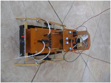
Berikut merupakan Pengontrol Robot yang dilengkapi LCD penampil data suhu real time yang dikirimkan oleh robot.

Gambar
dibawah merupakan robot mobil yang dikendalikan jarak jauh serta dapat
mengirimkan data suhu lingkungan karena dilengkapi dengan sensor suhu
LM35.

Berikut adalah video yang telah diunggah ke youtube
Robot kontrol wireless dapat juga diaplikasikan pada robot hexapod, seperti karya Profesor Bolabot berikut


Berikut adalah video robot hexapod bolabot
Copyright 2013@ Profesor Bolabot


Dimana dapat membeli tlp/rlp 315?
BalasHapusDimana dapat membeli tlp/rlp 315?
BalasHapus